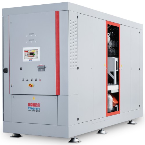
Cogeneration unit Sokratherm CHP Unit GG 710
Modern cogeneration unit that produces heat and power on-site, without transport losses. Due to its high efficiency and ability to quickly turn on and off, this unit is an ideal solution for stabilizing the energy grid and balancing fluctuations in renewable energy production.
Sokratherm CHP Unit GG 710 is a modern cogeneration unit that produces heat and power on-site, without transport losses. Due to its high efficiency and ability to quickly turn on and off, this unit is an ideal solution for stabilizing the energy grid and balancing fluctuations in renewable energy production.
| Characteristic | Value |
|---|---|
| Engine type | E3872 LE201 |
| Electrical power [kW] | 710 |
| Thermal power [kW] | 755 |
| Gas consumption [kW Hi] | 1671 |
| Electrical efficiency [%] | 42.5 |
| Thermal efficiency [%] | 45.2 |
| Total efficiency [%] | 87.7 |
| Power to heat ratio | 0.92 |
| Primary energy factor | 0.0 |
| Service interval [operating hours] | 1000 |
| Major overhaul after [hours] | 50000 |
| Length [mm] | 4200 |
| Width [mm] | 1700 |
| Height [mm] | 2600 |
| Operating weight [kg] | 9260 |
| Noise level [dB (A) at 1 m] | 75 |
Cogeneration and Trigeneration: What They Are and Their Benefits
Cogeneration is the simultaneous production of heat and electricity from a single energy source, significantly increasing overall fuel efficiency. Trigeneration additionally includes the production of cooling, making this approach even more versatile and efficient.
Benefits of Cogeneration:
- High fuel efficiency.
- Reduced energy costs.
- Minimal energy transport losses.
- Quick response to demand changes.
How Cogeneration and Trigeneration Work
A cogeneration unit operates on an internal combustion engine that drives a generator. The generated electricity is used on-site or fed into the grid, while the heat produced during combustion is used for heating, hot water supply, or industrial needs. In trigeneration, the additional heat is used to produce cooling via absorption chillers.
Advantages of Cogeneration Compared to Traditional Energy Production Methods
- Higher Efficiency: Cogeneration uses up to 90% of the fuel energy, whereas traditional methods use only about 50%.
- Flexibility: The ability to quickly turn on and off allows for better response to demand changes.
- Cost Savings: Reduced energy costs and lower infrastructure expenses.
Environmental Benefits of Cogeneration and Trigeneration
- Reduced CO2 Emissions: Higher fuel efficiency results in lower greenhouse gas emissions.
- Minimized Heat Losses: Using heat that is usually wasted reduces overall fuel consumption.
- Support for Renewable Energy: Stabilizing the grid during fluctuations in renewable energy production.
CHP (Combined Heat and Power Generation): What It Is
CHP, or cogeneration, is a technology that allows simultaneous production of heat and electricity from a single fuel source. The core component of a CHP unit is an internal combustion engine that drives a generator. The electricity can be consumed on-site or fed into the grid, while the heat is used for various needs such as heating and hot water supply.
Unit Sizes
To ensure high annual utilization, cogeneration units are typically sized based on the base heat load of the facility. This approach covers a significant portion of energy consumption, often more than half of the annual heat and power needs. Peak demands are covered by public grids and peak boilers.
Control Systems
The control system for CHP units from Sokratherm ensures complete control and automation of the cogeneration units' operation. It includes real-time monitoring and control functions, maximizing the efficiency and reliability of the units.
Advantages of Sokratherm CHP Units
- Compact Design: Ideal for installation in confined spaces.
- Minimal Installation Costs: Due to ready-to-connect construction with an integrated control panel.
- High Efficiency: Optimal use of fuel energy.
- Environmental Friendliness: Operating the engine in the range with the lowest emissions.
- Low Noise Levels: Excellent sound insulation and vibration decoupling.
- Automation: Fully automatic operation with internet-based remote monitoring and control.
- Reliability: High reliability and low operating and maintenance costs.
Increasing Thermal Efficiency with Condensing Heat Exchangers
At especially low return temperatures (below approximately 50°C), it is often sensible to gain additional heat from the exhaust gases. This can increase the regular thermal power of the unit by up to 15%, raising the total efficiency by several percentage points.
Cooling in Trigeneration
Our cogeneration units can be equipped with a 'Hot Cooling' function, allowing operation at increased flow temperatures up to 95°C. This is necessary for optimal operation of absorption chillers and other processes.
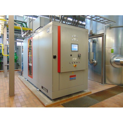
Installation in Containers or Substations
For special application cases, we offer our cogeneration units in weatherproof containers or concrete blocks, allowing them to be placed outside the main buildings.
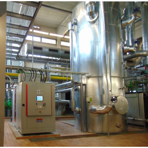
Steam Production
The heat generated by a cogeneration unit can be used to produce steam, necessary for industrial processes such as in food processing or breweries.
Emergency Power Supply
Our cogeneration units can provide emergency power by operating in island mode, supplying critical systems during a mains failure.
Buffer Heat Storage
Buffer heat storages improve the operation and profitability of cogeneration units by absorbing excess heat and providing it when needed. This enhances the efficiency and economic viability of the units.
Grid Control
The zero feed-in control ensures that the unit does not feed electricity into the public grid, adjusting production to match on-site consumption.
Compact cogeneration unit with synchronous alternator to generate three-phase current 400 V, 50 Hz, heating water at temperature level 90/70 °C and low-temperature heat 40/44.4 °C (LT-heat). Operation with natural gas, controlled lean operation with SCR catalytic converter system, emission values below the limit values of the 44th BImSchV. The performance data is valid for an altitude of up to 100 m above SL and an air temperature of up to 25 °C with a LT-return temperature of up to 40 °C.
| Operating Mode | Electric Power (gross) | Internal Power Consumption * | Electric Power (net) | Minimum Electric Power (partial load) | Heating Power (tolerance 8 %) | Gas Input (tolerance 5 %) |
|---|---|---|---|---|---|---|
| Mains Parallel Mode | 710 kW | 13 kW | 697 kW | 355 kW | 755 kW | 1671 kW |
| Standby Power System | 807 kVA | 686 kW | 1519 kW |
*) without external consumers, preliminary fuse in separate feed (if required): 63 A
Design and Scope of Supply
Engine with Accessories
- Engine Type: MAN E3872 LE201
- Combustion Method: Gas Engine
- Cycle: 4-stroke
- Number/Design of Cylinders: 12 / V-assembly
- Bore/Lift: 138/165 mm
- Displacement: 29.6 dm³
- Rotation Speed: 1500 rpm
- Average Piston Speed: 8.3 m/s
- Average Effective Pressure: 19.86 bar
- Compression Ratio: 13.3 : 1
- ISO Standard Rating per DIN ISO 3046-1: 735 kW
- Specific Full Load Consumption: 2.27 kWh/kWhmech.
- Full Load Consumption at Hi (Net Calorific) = 10 kWh/Nm³: 167.1 Nm³/h
- Average Consumption of Synthetic Oil (estimated): 200 g/h
Engine Description:
- Crankcase: with cylinder block made of one piece of cast iron, closed from below by oil tray, closed to the rear by flywheel timing case, exchangeable, wet cylinder liners, sealed twice.
- Single Cylinder Head: with integrated cooling water and oil ducts, cast-in spin suction ducts and shrunk valve seat rings and replaceable valve guides.
- Valves: arranged hanging, two valves one for outlet, valve stems made from carbide metal, camshafts with 7 bearings.
- Light Metal Pistons: cooled by pressurized oil stream via oil nozzles.
- Cracked Connecting Rods: crankshaft with 7 bearings and screw-on counterweights, bearing boxes with steel backside, leaded bronze liner, and ternary bearing surface.
- Double Flow Mixture Suction Pipe: one insulated exhaust fume collector and pressure oil lubricated exhaust turbocharger per cylinder bench, casing, and bearing bracket water-cooled.
- Water Cooled, Double-Stage Mixture Cooler.
- Gear Pump: for pressure lubrication, tandem lube oil filter in the main flow, cooling by oil cooler, automatic oil refill unit, and oil storage tank.
- Air Intake: via dry filter from the engine room.
- Crankcase Breather: with oil separator valve and connection to the air intake.
- Closed Cooling Water Circuit: with electrical three-phase circulating pump 400 V, safety valve, and expansion tank with pressure gauge for engine cooling.
- Electrical Starter: 24 V, 7 kW.
- Microprocessor-Controlled Ignition System: with one ignition coil per cylinder.
Gas Supply
Safety gas line in accordance with DVGW-VP 109, customer assembly above the unit, consisting of a bulk delivered ball-valve with thermal shutoff, filter, pressure gauge with push-button valve, two solenoid valves, pressure control valve, and flexible connecting tube, DVGW certified. Variable, step-motor-controlled gas/air mixer, electronic speed governor.
Gas Supply and Catalyst System
SCR-catalytic converter with oxidation catalyst for emission reduction according to the standards of the 44th BImSchV, catalyst body made of ceramic full extrudate. Lean operation, mixture formation based on load pressure and mixture temperature. Dosing unit with control, injector, mixing section (internally), catalyst housing, and day tank for urea (externally). Emission values after catalyst system in steady-state operation related to 5 % oxygen in the exhaust gas at rated power (as-new condition):
- NOx / CO: < 0.1* / 0.25 g/Nm³ *until 31.12. 2024 set to < 0.25 g/Nm³
- HC total / HCHO: < 1.3 g/Nm³ / 20 mg/Nm³
Urea consumption at nominal load: approx. 2.4 l/h
Exhaust Silencer
Primary and secondary exhaust silencer made of stainless steel to reduce the exhaust noise level as recommended accessories for on-site installation in the exhaust pipe.
Alternator
Inner-pole alternator, air-cooled, protection class IP 23, build design B3/B14, according to VDE 0530, radio suppression grade N. Synchronous alternator with integrated field coil, absorber cage, and compound, brushless, two-layer winding, low harmonic content design, insulation class H.
- Rated Output: 1125 kVA
- Rated Current (nom. power, cos φ 0.8): 1281 A
- Efficiency Rate (nom. power): 96.6 %
- Cos φ: 1.0
- Operating Mode: Star
- Ambient Temperature, Max.: 40 °C
- Voltage: 400/231 V
- Frequency / Rotation Speed: 50 Hz / 1500 rpm
Coupling
Engine and alternator connected rigidly by SAE housing and interconnecting flange. Flexible coupling between engine flywheel and alternator shaft. Replacing the flexible intermediate ring is possible without disassembling both engine and alternator.
Base Frame and Pipework
Base frame as torsion-resistant, versatile profile steel construction used to carry engine/alternator as well as the following components of the CHP unit:
- pump for engine cooling circuit,
- separate cooling water pump for the first stage of mixture intercooler,
- heat exchangers for engine cooling circuit and exhaust,
mounted ready for operation in the base frame, with complete pipework and insulated as far as required. If required for mounting in the heating water return: heating water circulating pump and 3-way valve for return temperature lifting, designed for operating data according to para. 3.5.
Sound Absorbing Case
Powder-coated steel plate casing with highly effective sound-absorbing lining with elastic supporting and a controlled fan for ventilation of the canopy. Easily accessible due to removable cowls on all sides with quick-lock mechanisms. Base frame decoupled with Sylomer strips from the canopy.
Switch Cabinet, Integrated Compactly Within the Sound Absorbing Case
Power section according to VDE AR-N 4110:2018, on request VDE AR-N 4105:2018 (grid monitoring, synchronization, alternator contactor, and power switch protected with add. shunt release, wear-free mains starter), iPC for unit control and monitoring (with 10.1'' color TFT touchscreen display (opt. 15.6'') incl. control ''MiniManager'', opt. remote monitoring system ''RemoteManager''), ready to use and wired. For details please view separate technical descriptions.
Cooling Water Heat Exchanger Incl. First Stage of Mixture Intercooler (HT-heat)
The engine cooling water heat is transferred to the heating water via a plate heat exchanger.
- Material: 1.4401
- Thermal Output from Engine Cooling (8 % tolerance): 407 kW
- Heating Water Temperature Inlet/Outlet: 70/82 °C
- Pressure Drop (Heating Circuit): 370 mbar
- Cooling Water Temperature Inlet/Outlet (in as-new condition): 80/86 °C
- Flow Rate (Engine Cooling Circuit): 44.2 m³/h
- Cooling Water Pump Load (highly efficient according to ErP2015): 3.8 kW
Exhaust Heat Exchanger (plain delivered)
The exhaust heat of the engine is transmitted to the heating water by a tube-type exhaust heat exchanger for on-site installation in the exhaust and heating water pipe.
- Material: 1.4571 / P235
- Thermal Output (8 % tolerance): 300 kW
- Exhaust Gas Temperature Inlet/Outlet (as new condition): 370/120 °C
- Heating Water Temperature Inlet/Outlet: 82/90 °C
- Pressure Drop (Exhaust Side): 15 mbar
- Pressure Drop (Heating Circuit): 230 mbar
If required, an additional exhaust gas heat exchanger is available for use of condensation heat, mounting on the side of the customer. The additional heat output of this heat exchanger (components touching the exhaust gas made of stainless steel 1.4571) is up to 147 kW.
Second Stage of Mixture Intercooler (LT-heat)
The LT mixture cooler heat must be integrated into a low-temperature heating circuit by the customer or eliminated via a separate cooler. In this case, the inlet temperature must be controlled constantly and the minimum volume flow must be ensured. Tube assembly heat exchanger, material Cu
- Thermal Output (8 % tolerance): 48 kW
- Cooling Water Temperature Inlet/Outlet: 40/44.4 °C
- Pressure Drop Cooling Water: 300 mbar
Optional: connection set consisting of a circulation pump, 3-way valve with control, and blast cooler for mixture cooling.
Technical Data and Elucidations for Planning and Operation
Fuel
Natural gas of normal composition, free of phosphorus, sulfur, halogens, arsenic, and heavy metals as well as solids and liquids, with constant fuel value and pressure and according to the rules of the DVGW sheet G260.
- Lower Limit for Lower Calorific Value (Hi): 10 kWh/Nm³
- Methane Number: > 80
- Permissible Hydrogen Content in Natural Gas (mixture): max. 20 Vol.%
- Gas Flow Pressure Range (overpressure, constantly): 20 - 100 mbar
- Gas Temperature: 10 - 30 °C
Operating values for other fuel compositions and conditions on request. We recommend using a gas warning system in the operating room (on the side of the customer).
Combustion Air and Ventilation
- Combustion Air Requirement: 2819 Nm³/h
- Air Supply, in Total: approx. 14720 m³/h
- Inlet Air Temperature Min./Max.: 10/30 °C
- Heat Radiation from Casing Surface: approx. 9 kW
- Heat Ventilation from Within Casing: approx. 66 kW
- Exhaust Air: approx. 11900 m³/h
- Exhaust Air Temperature: 50 °C
- Free Pressing of Exhaust Air Fan at Operating Point (max.): 250 (835) Pa
- Electric Load of Fan at Operating Point (max.): 2710 (4700) W
Highly efficient radial fan (according to ErP2015) with EC-motor and temperature-controlled regulation, if required with connection box. Operating ventilation system above standard conditions is not possible and leads to increased power consumption, sound level, and operating temperature.
Exhaust Gas
- Exhaust Gas Flow Rate at 120 °C: 4300 m³/h
- Permitted Back Pressure after Unit: 20 mbar
A continuous condensate drain must be installed in the connected exhaust gas system. For multi-unit systems, each unit has to be equipped with a separate exhaust gas system.
Sound Levels
- Sound Level of Engine (with/without sound-absorbing case): 75/91 dB(A)
- Exhaust Sound Level after Optional Exhaust Gas Silencer: 78 dB(A)
- Exhaust Sound Level after Optional Secondary Exhaust Silencer: 60 dB(A)
- Ventilation Air Sound Level after Fan (Operating Point): 92 dB(A)
Free-field sound pressure values at a 1 m distance. The triple shock absorption of the CHP unit reduces the impact sound transmission to a minimum. A foundation for installing the CHP is not necessary if the engine room floor can carry the load of the CHP unit and the unit is set on the foundation plate of the building.
Heat Production
The HT-heat (motor cooling, exhaust, and mixture cooling) as well as the LT-heat both have to be utilized on part of the customer at all operating points. Layout data:
- LT Heating
- Return Temperature to Unit (Min./Max.): 40 °C 60/70 °C
- LT: min. / heating: std. flow rate: 9.5 m³/h 30.4 m³/h
- LT: max. / heating: max./std. temperature increase: 4.54 K 30/20 K
- Pressure Drop: 0.30 bar 0.60 bar
- Operating Pressure (Min./Max.): 1.5/6 bar 1.5/6 (optional 10) bar
The return connections have to be equipped with a strainer with a mesh size of 0.25 mm.
Filling Quantities and Quality Demands
- Oil Tray: 90 liters
- Oil Storage Tank: 105 liters
- Engine and Heat Exchanger Coolant: 120 liters
(Lubricating oil and coolant have to fit separate release lists.)
- Heating Water: 200 liters
Treatment of the contents, additional, and rotating heating water according to VDI guideline 2035 (group 4) with the following limits:
- Total Earth-Alkaline /Total Hardness: < 0.02 mol/m³ / < 0.1 °dH
- pH-Value: 9 - 10.5
- Molecular Conductance (at 25 °C): < 250 μS/cm
- Oxygen Content: < 0.02 mg/l
- Chloride Content: < 20 mg/l
- Filterable Substances: < 2 mg/l
Appearance: colorless, clear, and free of mechanical impurities. Use of oxygen binders should be avoided if possible.
Dimensions, Connections and Weight
- Length (Basic Measurements): 4200 mm
- Width: 1700 mm
- Height: 2600 mm
- Operating Weight: 8160 kg
- Dry Weight: 7670 kg
- Heating Water Inlet/Outlet: DN 80 (PN 10)
- Mixture Cooler Flow/Return: R 2" (i)
- Gas Regulation Unit (flange): DN 65 (PN 16)
- Condensate: R ½" (a)
- Exhaust (flange): DN 250 (PN 10)