-default-500x500.jpg)
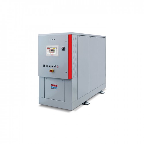
Когенераційна установка Sokratherm CHP Unit GG 50 (VR версія)
The CHP Unit GG 50 (VR version) is a modern cogeneration unit that produces heat and power on-site, without transport losses. Due to its high efficiency and ability to quickly turn on and off, this unit is an ideal solution for stabilizing the energy grid and balancing fluctuations in renewable energy production.
The CHP Unit GG 50 (VR version) is a modern cogeneration unit that produces heat and power on-site, without transport losses. Due to its high efficiency and ability to quickly turn on and off, this unit is an ideal solution for stabilizing the energy grid and balancing fluctuations in renewable energy production.
| Characteristic | ||
|---|---|---|
| Engine type | E0836 E302 | E0836 E302 |
| Electric power [kW] | 50 | 50 |
| Thermal power [kW] | 101 | 84 |
| Gas consumption [kW Hi] | 145 | 145 |
| Electric efficiency [%] | 34.5 | 34.5 |
| Thermal efficiency [%] | 69.7 | 57.9 |
| Total efficiency [%] | 104.2 | 92.4 |
| Power to heat ratio | 0.49 | 0.58 |
| Primary energy factor | 0.221 | 0.265 |
| Maintenance interval [hours] | 2000 | 1500 |
| Overhaul after [hours] | 60000 | 60000 |
| Length [mm] | 2500 | 2200 |
| Width [mm] | 900 | 900 |
| Height [mm] | 1830 | 1830 |
| Operating weight [kg] | None | 2460 |
| Noise level [dB (A) at 1 m] | None | 62 |
Cogeneration and Trigeneration: What They Are and Their Benefits
Cogeneration is the simultaneous production of heat and electricity from a single energy source, significantly increasing overall fuel efficiency. Trigeneration additionally includes the production of cooling, making this approach even more versatile and efficient.
Benefits of Cogeneration:
- High fuel efficiency.
- Reduced energy costs.
- Minimal energy transport losses.
- Quick response to demand changes.
How Cogeneration and Trigeneration Work
A cogeneration unit operates on an internal combustion engine that drives a generator. The generated electricity is used on-site or fed into the grid, while the heat produced during combustion is used for heating, hot water supply, or industrial needs. In trigeneration, the additional heat is used to produce cooling via absorption chillers.
Advantages of Cogeneration Compared to Traditional Energy Production Methods
- Higher Efficiency: Cogeneration uses up to 90% of the fuel energy, whereas traditional methods use only about 50%.
- Flexibility: The ability to quickly turn on and off allows for better response to demand changes.
- Cost Savings: Reduced energy costs and lower infrastructure expenses.
Environmental Benefits of Cogeneration and Trigeneration
- Reduced CO2 Emissions: Higher fuel efficiency results in lower greenhouse gas emissions.
- Minimized Heat Losses: Using heat that is usually wasted reduces overall fuel consumption.
- Support for Renewable Energy: Stabilizing the grid during fluctuations in renewable energy production.
CHP (Combined Heat and Power Generation): What It Is
CHP, or cogeneration, is a technology that allows simultaneous production of heat and electricity from a single fuel source. The core component of a CHP unit is an internal combustion engine that drives a generator. The electricity can be consumed on-site or fed into the grid, while the heat is used for various needs such as heating and hot water supply.
Unit Sizes
To ensure high annual utilization, cogeneration units are typically sized based on the base heat load of the facility. This approach covers a significant portion of energy consumption, often more than half of the annual heat and power needs. Peak demands are covered by public grids and peak boilers.
Control Systems
The control system for CHP units from Sokratherm ensures complete control and automation of the cogeneration units' operation. It includes real-time monitoring and control functions, maximizing the efficiency and reliability of the units.
Advantages of Sokratherm CHP Units
- Compact Design: Ideal for installation in confined spaces.
- Minimal Installation Costs: Due to ready-to-connect construction with an integrated control panel.
- High Efficiency: Optimal use of fuel energy.
- Environmental Friendliness: Operating the engine in the range with the lowest emissions.
- Low Noise Levels: Excellent sound insulation and vibration decoupling.
- Automation: Fully automatic operation with internet-based remote monitoring and control.
- Reliability: High reliability and low operating and maintenance costs.
Increasing Thermal Efficiency with Condensing Heat Exchangers
At especially low return temperatures (below approximately 50°C), it is often sensible to gain additional heat from the exhaust gases. This can increase the regular thermal power of the unit by up to 15%, raising the total efficiency by several percentage points.
Cooling in Trigeneration
Our cogeneration units can be equipped with a 'Hot Cooling' function, allowing operation at increased flow temperatures up to 95°C. This is necessary for optimal operation of absorption chillers and other processes.
Installation in Containers or Substations
For special application cases, we offer our cogeneration units in weatherproof containers or concrete blocks, allowing them to be placed outside the main buildings.
Steam Production
The heat generated by a cogeneration unit can be used to produce steam, necessary for industrial processes such as in food processing or breweries.
Emergency Power Supply
Our cogeneration units can provide emergency power by operating in island mode, supplying critical systems during a mains failure.
Buffer Heat Storage
Buffer heat storages improve the operation and profitability of cogeneration units by absorbing excess heat and providing it when needed. This enhances the efficiency and economic viability of the units.
Grid Control
The zero feed-in control ensures that the unit does not feed electricity into the public grid, adjusting production to match on-site consumption.
A compact cogeneration unit with a synchronous generator for generating three-phase current of 400 V, 50 Hz, and heating water to a temperature of 90/70 °C. A return pipe and a controlled pump are installed to maintain a constant temperature. Operates on natural gas with a three-way catalyst for low emissions λ = 1, emission values comply with BImSchG § 22. Technical specifications are valid for an altitude of up to 100 m above sea level and an air temperature of up to 25 °C.
| Characteristic | ||
|---|---|---|
| Engine type | E0836 E302 | E0836 E302 |
| Electric power [kW] | 50 | 50 |
| Thermal power [kW] | 101 | 84 |
| Gas consumption [kW Hi] | 145 | 145 |
| Electric efficiency [%] | 34.5 | 34.5 |
| Thermal efficiency [%] | 69.7 | 57.9 |
| Total efficiency [%] | 104.2 | 92.4 |
| Power to heat ratio | 0.49 | 0.58 |
| Primary energy factor | 0.221 | 0.265 |
| Maintenance interval [hours] | 2000 | 1500 |
| Overhaul after [hours] | 60000 | 60000 |
| Length [mm] | 2500 | 2200 |
| Width [mm] | 900 | 900 |
| Height [mm] | 1830 | 1830 |
| Operating weight [kg] | None | 2460 |
| Noise level [dB (A) at 1 m] | None | 62 |
Operating Mode
| Operating Mode | Electric Power (gross) | Internal Consumption | Electric Power (net) | Minimum Electric Power (partial load) | Thermal Power (tolerance 8 %) | Gas Input (tolerance 5 %) |
|---|---|---|---|---|---|---|
| Parallel to the grid | 50 kW | 1 kW | 49 kW | 25 kW | 84 kW | 145 kW |
| Backup mode | 57 kVA | - | - | - | 76 kW | 132 kW |
* without external consumers, preliminary fuse in separate power supply (if needed): 63 A
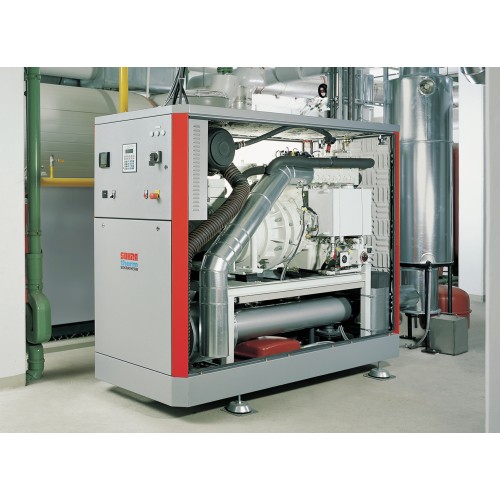
Construction and Equipment
Engine with Accessories
- Engine type: MAN E0836 E302
- Combustion method: Gas engine
- Cycle: 4-stroke
- Number/arrangement of cylinders: 6 in-line
- Bore/stroke: 108/125 mm
- Volume: 6.87 l
- Speed: 1500 rpm
- Average piston speed: 6.3 m/s
- Average effective pressure: 9.43 bar
- Compression ratio: 13 : 1
- ISO standard according to DIN ISO 3046-1: 54 kW
- Specific consumption at full load: 2.69 kWh/kWh
- Consumption at full load Hi (lower calorific value) = 10 kWh/nm³: 14.5 nm³/h
- Average synthetic oil consumption (estimate): 25 g/h
Engine Description:
- Crankcase: with a solid cast iron cylinder block, closed at the bottom with an oil pan.
- Double cylinder head: with integrated channels for cooling water and oil.
- Valves: monoaxial, steel, carbide.
- Pistons: light alloy, cooled by an oil jet.
- Crankshaft: with five bearings, forged counterweights.
- Intake manifold: single-flow, water-cooled.
- Oil pump: with a tandem filter.
Gas Supply
- Safe gas line according to DVGW-VP 109, vibration-separated connection with support angles on the roof of the soundproof housing, consisting of a ball valve with thermal shutdown, filter, pressure gauge with push-button valve, two solenoid valves, pressure regulator, gas regulator and flexible connecting tube, certified by DVGW. Gas/air mixer with static Venturi insert, electronic speed controller.
Gas Supply and Catalyst
- Lambda sensor: for automatic air/fuel ratio regulation.
- Catalyst: for reducing emissions in accordance with German BImSchG standards, designed as a three-way catalyst for operation at lambda = 1.
- Exhaust silencer: combined reflective-absorbing stainless steel exhaust silencer for reducing exhaust noise, recommended accessory for on-site installation.
Generator
- Synchronous generator with internal pole, air cooling, protection class IP 23, B3/B5 design according to VDE 0530.
- Rated power: 82 kVA
- Rated current (rated power, cos φ 0.8): 90 A
- Efficiency (rated power): 94.4%
- Cos φ: 1.0
- Operating mode: Star
- Ambient temperature, max.: 40 °C
- Voltage: 400/231 V
- Frequency / speed: 50 Hz / 1500 rpm
Coupling
- Engine and generator are rigidly connected using an SAE housing and interflange connection. Flexible connection between the engine flywheel and the generator shaft.
Main Frame and Piping
- The main frame as a rigid profile construction is used for placing the engine/generator and the following components of the CHP unit: pump for the engine cooling circuit, heat exchangers, controlled circulation pump, and 3-way valve.
Soundproof Housing
- Powder-coated steel housing with a highly efficient soundproofing layer, ventilation fan with controlled temperature mode.
Control Cabinet
- Integrated control cabinet with power section according to VDE AR-N 4105:2018, on request VDE AR-N 4110:2018 (network control, synchronization).
Cooling Water Heat Exchanger
- Engine cooling water heat is transferred to the heating water through a plate heat exchanger.
- Material: 1.4401
- Heat power from engine cooling (8% tolerance): 48 kW
Exhaust Gas Heat Exchanger
- Exhaust gas heat is transferred to the heating water through a water-cooled exhaust gas manifold and tubular heat exchanger.
- Material: 1.4571 / P235
- Heat power (8% tolerance): 36 kW
- Exhaust gas temperature inlet/outlet (new condition): 620/100 °C
Technical Data and Planning and Operation Explanations
-
Fuel: Natural gas of normal composition, without phosphorus, sulfur, halogens, arsenic and heavy metals, as well as solid and liquid particles, with constant calorific value and pressure.
- Lower limit of lower calorific value (Hi): 10 kWh/nm³
- Methane number: > 80
-
Combustion Air and Ventilation:
- Combustion air requirement: 137 nm³/h
- Inlet air temperature min./max.: 10/30 °C
-
Exhaust Gases:
- Exhaust gas volume at 100 °C: 220 nm³/h
-
Noise Levels:
- Engine noise level (with/without soundproof housing): 62/81 dB(A)
-
Heat Production:
- Return temperature to the unit (min./max.): 40/70 °C
-
Fill Volumes and Quality Requirements:
- Oil pan volume: 13 liters
- Oil reservoir volume: 59 liters
- Engine and heat exchanger coolant volume: 19 liters
- Water treatment requirements for heating: according to VDI 2035 directive (group 4).
Dimensions, Connections, and Weight:
- Length (basic dimensions): 2200 mm
- Width: 900 mm
- Height: 1830 mm
- Operating weight: 2460 kg